Overview and operating instructions for the CNC mill 3 upgrade using the TRAK TMC7
Table of contents
Overview

The Trak TMC 7 is a fully enclosed 3 axis cnc milling machine with a 16 station Automatic tool changer(ATC) intended for larger, more complicated work.
The TMC 7 has a table size of 35.43” x 19.69” with travel limits in X 30”(762 mm), Y 20”(508 mm) and Z 20”(508 mm).
This machine has a spindle speed range from 50 rpm to 8000 rpm with a maximum rapid feed at 1000 ipm.
This machine is equipped with the RMX controller that has a lot of the same capabilities as the SMX on the DPM and the TMX on the 2 op, but has a few more options.
It has conversational programming along with uploading cad/cam, dxf and parasolid files.
You will be able to read more in the Enhanced ProtoTRAK Assistance (EPA)tab.
Tools and Tool Holders
The TMC 7 requires the use of cat 40 tool holders with retention knobs. Below are pics of the tool cart and the different types of cat 40 tool holders and their use.
Tool Cart
The tool holders are located on the designated tool cart for the TMC 7 as shown in the pic below.

Keyless chuck- spot drills, drills, edge finders, etc.

Collet chucks- uses E32 collets for spot drills, drills, counterbores, reamers, countersinks, endmills.

Endmill holders- endmills and tools with flats.
Sizes include 1/4",3/8",1/2",5/8",3/4"and 1". You can not use these holders unless the tool has the flat.
.JPG "endmill holder")
Indexable Face mill- 5" dia(in the pic below).
We also have a 4"and 3"dia.

Indexable Square Shoulder Mill- 1 1/2"dia(pic below).
We also have a 4"and a 1"dia.

Tap Chuck- Large tension tapping chuck w/ adapters for 5/16-7/8 (shown below).
We also have a small tension tapping chuck w/ adapters for #0-9/16.

Tool holding clamp- used to mount tools in the holders.

Reference Tool or Base Tool- used in conjunction with the tool setter and the 2x4x6 block(in the pics below).

Tool Setter- used to set base tool and Z offsets for each tool in the Tool Table.

2x4x6 Block- used as a riser block for the tool setter.

Tool Setter on 2x4x6 Block- these will be used to set the base tool and all tools in the program, much like setting the tools on the 2 OP.

Power up the TMC 7
Turn "ON" the main power switch, located on the right side of the machine, as shown in the pics below.
.jpg "power off")
.jpg "mainswitchon")
Go to the back of the machine on the left side and move the valve hand down to turn the air on, it is the copper line on the wall.
Control screen
Press and hold the Power/Reset soft key until the white led light comes on to enable the servos.
You will hear the lube pump start up and a green box with the message "Enabling servos, please wait".
.jpg "rmxscreen")

Press the set home soft key right below the content screen highlighted in the pic below.
A message will appear on the content screen "Close the door and press go when ready" as shown in the pic below.
The machine will now go the machine home position.
Press the warm up soft key highlighted in the pic below.
Next follow the prompts on the screens in succession to proceed with the warm up phase, please select the 10 Minute warmup.
To use the Electric Hand Wheel, press the EHW button located in the middle of the control panel. Next press the Z axis button.
Once activated, the led lights for the EHW, the Z axis, and the resolution will be lit up for identification as shown in the pic below.
Use the EHW to lower the Z axis so the spindle is at least 8" above the tallest vise as shown in the pic below, but also making sure that it will not hit a part or vice while moving during the warm up cycle, the machine will traverse back and forth and up and down during the warm up cycle.
Now press the Set Z soft key. This is the lowest position the Z will travel during the warmup.
Enhanced ProtoTRAK Assistance(EPA)
(This info is only for reference, seek staff for questions if needed)
EPA is a collection of tutorials that will provide quick and easy access of all the ProtoTRAK features.
You will use the tutorials in EPA whenever you are using the TMC.
Press the EPA soft key located on the left side of the screen under the info column.
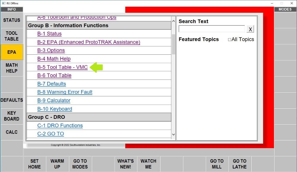
Group B information functions will be the first screen that will appear.
Tap on the B-2 EPA link to go through the general information on it's use as shown in the pic below.
Follow the steps in the link to access all of the tutorials.
Please read the red text at the bottom of step 1, shown in the pic below.
You will notice that there are 2 tutorial links for the tool table in EPA. Use the Tool Table -VMC link to access the tool table tutorial for this machine because it is equipped with an 16 station automatic tool changer.
Create or Open a program before setting tools
Load a program by first inserting the USB thumb drive into the slot on the right side of the controller. *Do not touch the USB drive in the top slot indicated by the red X, this is used for the controller software.*

Load the program from the USB drive by selecting the "PROG IN/OUT" button. Within the menu shown below, navigate to the proper folder on the drive and select your program. Change file types and navigate folders using the touch screen. With your program selected, press OPEN and the program will load into the controller. The training program is a .GCD file not a .CAM file like the photo shows.
.CAM files tend to make the machine hang up or freeze while trying to load.
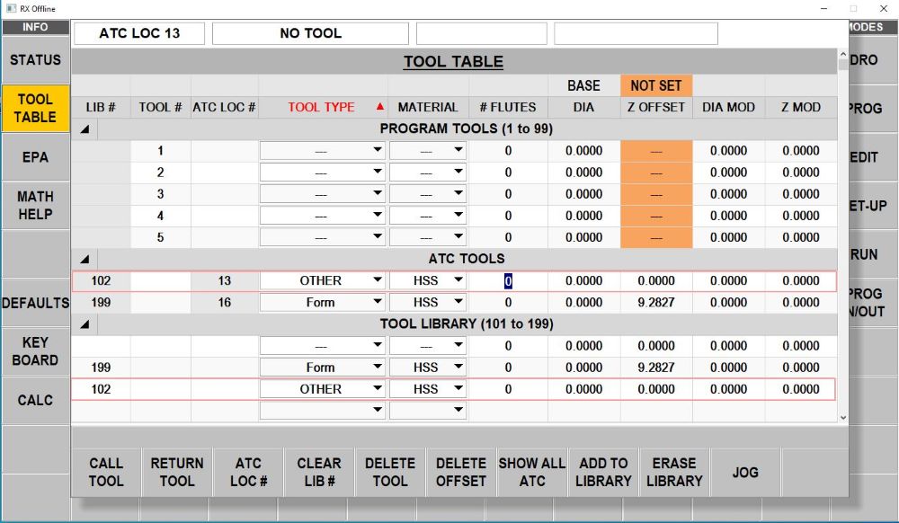
Once the program is loaded on the controller, open the TOOL TABLE. If the program was properly loaded, the program tools section should be present, as seen below. Check with staff or see the lab instructions page to confirm the order of your tools. If there is no program created or loaded, there will not be a program tools section in the tool table.
Loading the reference(base) tool into the spindle
Press the tool table soft key.
The reference(base) tool will be labeled as a form tool in the tool library and in location #16 in the ATC.
Tap on tool and press call tool soft key as shown in the pic below.
Now follow the prompt on the screen below to call up the reference(base) tool from the ATC to the spindle.
The reference tool will now be loaded into the spindle from the ATC.
The status bar(highlighted in the pic below) will display that tool information.
Setting the reference tool
1) Place a 2x4x6 block on the table, with the 6" side vertical, make sure the table is clean of chips and coolant, then set the tool setter on top.
2) Wipe off the Base tool tip to make sure it is clear of dirt, chips, and coolant, having stuff on there will affect the accuracy of all the other tools.
3) Move the reference tool to about an inch above the tool setter and off to the side, see photo below, using the EHW (Electronic Hand Wheel). This ensures that we are never moving a tool straight down on the tool setter and accidentally crashing down onto it if we have the resolution incorrectly set.
4) Now lower the resolution and bring the reference tool to the center of the tool setter using X,Y, and Z.
5) Lower the Z until the tool setter reads all zeros like the photo below.
Tap on the NOT SET box as shown in the pic below. It will change from beige to blue as shown in the pics below.
Now press ABS SET to set the base tool in the tool table.
The base will go from not set to set with a green back drop, as shown in the pic below, the Z offset will be 0.0000 not 9.2827 like the photo shows.
Press the return tool soft key to put the reference tool back into the ATC.
Manually loading tools into the spindle
Start with tool #1 in your program.
Place the tool in the spindle and hold it in place. Now press and hold the green button until the holder moves up and locates the spindle drive keys into the notches on the holder as shown in the pic below.
NOTE: Do not let go of the tool until it is located correctly and secured in the spindle.
Setting tool offsets and loading tools in ATC
1) Fill out the drop down boxes for tool 1 if not done already as shown in the pic below.
2) Follow the same directions for setting the Z offset for tool 1 as you did for setting the base tool earlier in this procedure.
3) Make sure to set all tools to zero on the tool setter, then press ABS set for each tool needed, the Z offset will not be 0.0000 like in the photo.
4) Move the tool away from the tool setter in the Z axis.
5) Give that tool an empty ATC location number. Make sure that location is empty.
6) Tool is already in the spindle so press yes.
Follow the prompt on the screen below to add the tool from the spindle to Loc 1 into the ATC.
Notice that the tool has been added to the ATC tools section of the tool table.
Follow the steps noted above to touch off all program tools in order and to place them in the ATC.
Make sure the tools are in the correct order in the tool table and the ATC or the Z offsets will be off!
Requirements before Running programs
1) Staff will have to verify and post any cam files before loading into to the controller.
2) Use the instructions stated previously in this guide to set the reference tool and program tools in the tool table.
3) Secure stock in the machine and use the edge finder to set X, Y origins.
4) Call tool 1 into the spindle and set Z 0 at the top of the stock.
5) Verify your program by referring to section E-5 Verify in the EPA.
6) Refer to the EPA as a resource guide if you have questions. (Seek staff first)
7) Have staff check your set up before running the program.
1) Press the RUN soft key. Press the START soft key. Press the TRAKing soft key.
2) TRAKing is a safety feature used to make sure that Z zero on the part and the Z offset for that tool are set correctly.
3) Use the hand wheels to slowly bring the tool down to the top of the part, right hand wheel is the coarse movement, and the left is fine movement.
4) Once the tool lightly touches the top of the part, the Z axis should read approximately 0, watch the DRO while moving the tool down to part and make sure the numbers are adding up, meaning, if you are about an inch from the top of your part and the DRO in Z says something drastically different then stop and get staff to verify!!
5) If it is significantly off, stop and reset the Z zero with the current tool.
6) Once you have determined that the Z is correct, you are able to use CNC RUN.
7) Hold the run pendant in one hand while running in CNC mode. Pressing the button on the pendant is the fastest way to stop the machine if you need to.
8) Once the operation is done and the tool change for the next tool is complete, press the button on the pendant to stop the machine to put back in TRAKing.
9) Press TRAKing and follow the directions previously done with the tool before.
10) Use TRAKing at the start of each operation.
11) If you refer to section H-3 TRAKing in the EPA, it only explains the use of the EHW.
12) Below is a pic of the handwheels in the front of the machine you can use in TRAKing.
Note: the Y axis hand wheel is used for slower feed and the X axis hand wheel is the faster feed.
Note: Measure your part before removing from the vise. If adjustments need to be made, you will not have to re do your set up.
Remove your part and parallels from the vise.
Remove the program tools from the ATC by calling up the tools and deleting from the library. Don't just manually take them out.
Press the coolant button and use the the coolant hose hanging from the controller to spray any chips down to the bottom of the machine.
Press the wash button to wash the chips out of the back of the machine to the chip auger.
Press the chip removal FWD button to turn on the chip auger.
Now wipe the residual coolant off the table using a rag.
Press the BACK button twice to get back to the original RMX screen.
Now press the SHUT DOWN soft key and let the controller boot down.
Now turn the main power switch off and shut the air valve off when finished.
Have staff check the machine before you leave.


calltool1.JPG "calltool")
toolchange.JPG "toolchange")

too1993.jpg "tooldescript")


setbasetool.JPG "basetoolset'")


